A chemical injection quill needs to fit the process, not just the pipeline connection. Its position, materials, mounting arrangement and maintenance access all affect the suitability of the installation.
Planning these details before installation helps avoid problems such as insufficient removal clearance, incompatible connections or an assembly that cannot be serviced as intended.
This guide covers the design checks and maintenance considerations to review with your supplier and engineering team. Specific installation steps, tightening values and retrieval procedures must follow the instructions for the supplied equipment.
What to Confirm Before Installing an Injection Quill
Start with an approved specification and drawing for the actual installation.
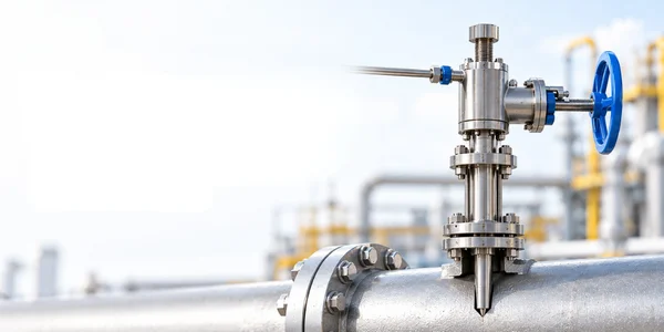
A chemical injection quill assembly may include the probe, mounting connection, seals, isolation valves and an optional check valve. Confirm which components are supplied and which belong to the site piping package.
Before installation, check:
- Equipment identification against the approved documents.
- Chemical and process-fluid compatibility.
- Operating and design pressure and temperature.
- Process and chemical-inlet connections.
- Probe dimensions and specified outlet position.
- Required installation and maintenance clearance.
- Applicable inspection and testing requirements.
NND Oil & Gas offers chemical injection quill configurations for review against these application requirements.
Do not substitute a similar-looking assembly without checking its specification.
Selecting the Position of an Injection Quill in Piping
The location should support the intended treatment duty and provide practical access.
An injection quill in piping introduces chemical at a specified position within the process stream. Its location should be assessed alongside the fluid conditions and required downstream distribution.
Avoid choosing a point solely because a convenient nozzle is available.
Review the Proposed Location for:
- Suitability for the chemical injection duty.
- Available pipeline and connection information.
- Access to valves and chemical-feed connections.
- Clearance around nearby structures and equipment.
- Space for the intended inspection or removal task.
The location review should involve both process and maintenance requirements. A position that is accessible during construction may become difficult to service once surrounding equipment is installed.
Insertion Length and Nozzle Orientation
Insertion length should be established from the installation geometry and approved design.
Nominal pipe size alone does not define the distance between the external connection and the intended outlet position. Nozzle stand-off, connection dimensions and assembly construction also need consideration.
Ask the supplier to identify:
- Overall probe length.
- Required insertion dimension.
- Outlet position.
- Orientation or alignment markings.
- Any applicable restrictions.
Nozzle orientation is design-specific. Manufacturer manuals provide instructions for their particular tip geometry; those instructions should not be transferred automatically to another model.
Do not shorten, modify or reposition a probe without an approved engineering review.
Flanged Injection Quill Connection Checks
A flanged injection quill requires a compatible mating connection and an agreed joint specification.
Matching the nominal size does not complete the check. The flange standard, pressure class, facing, materials and sealing arrangement must also be reviewed.
|
Connection Item |
What to Confirm |
| Flange size | Matches the approved pipeline connection |
| Standard and class | Consistent with the project specification |
| Facing | Compatible mating faces |
| Gasket | Suitable material, dimensions and service rating |
| Fasteners | Specified grade, size and condition |
| Assembly procedure | Approved tightening sequence and values |
| Access | Space for tools and later maintenance |
A flange class should not be treated as a universal operating-pressure value. Allowable conditions depend on the materials, temperature and complete joint.
Threaded and welded connections likewise require their own approved installation requirements.
Review the Chemical Feed Connection
The chemical line and quill should be assessed together.
Confirm connection compatibility, wetted materials and the required valve arrangement. Identify where the site’s piping responsibility ends and the supplier’s assembly begins.
For a complete package, review the chemical dosing system so the pump, tank, piping and injection equipment have a coordinated technical scope.
Check valves, isolation valves and pressure-protection devices perform different functions. Their purpose and inclusion should be stated clearly rather than assumed from the general assembly description.
Plan Maintenance Access Before Installation
Maintenance access should be designed into the layout.
For fixed equipment, identify the plant conditions needed for removal. For retractable equipment, confirm the complete withdrawal arrangement, required tools and available clearance.
Do not assume every retractable assembly permits removal under the same operating conditions. Retrieval equipment can have specific procedural and personnel requirements, as illustrated by manufacturer operating manuals.
Questions for the Layout Review
- Can personnel reach the equipment and operate its valves?
- Is full removal or withdrawal clearance available?
- Can required tools be positioned?
- What handling arrangements are needed?
- Are service components accessible?
- Which isolation and operating procedures apply?
Resolve these questions before the installation is accepted.
Commissioning and Handover Checks
Commissioning should follow the project’s approved procedures and the supplied equipment instructions.
The handover review should confirm that the installed arrangement matches the approved documents and that the required checks have been recorded.
Useful records include:
- Final equipment and drawing references.
- Confirmed materials and connections.
- Inspection and test results.
- Operating instructions.
- Maintenance requirements.
- Spare-parts information.
- Responsibilities for outstanding work.
Keep a record of the initial operating conditions. This provides context when reviewing later changes in dosing performance.
Chemical Injection Quill Inspection and Maintenance
Maintenance requirements depend on the chemical, process conditions, assembly design and service history.
Follow the manufacturer’s guidance and the site’s maintenance programme rather than applying an arbitrary interval.
| Inspection Area |
Points for Review |
| External condition | Visible damage, corrosion or leakage indications |
| Connections | Condition assessed under the approved inspection procedure |
| Operating performance | Changes from the recorded dosing conditions |
| Valves and seals | Service requirements and replacement history |
| Probe and outlet | Condition when inspection access is available |
| Documentation | Correct model, drawing and replacement-part references |
Any cleaning method must be compatible with the chemical and equipment materials. Do not open, tighten or dismantle a pressurised assembly as a general troubleshooting response.
Common Installation and Maintenance Mistakes
Ordering by Connection Size Alone
Also confirm materials, dimensions, operating limits and maintenance arrangements.
Leaving Insufficient Withdrawal Space
Check the full maintenance requirement, not only the installed equipment footprint.
Treating a Check Valve as Maintenance Isolation
Establish the required isolation arrangement separately.